

 français


Connaissances de base et application des vannes
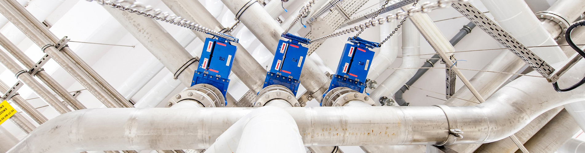
Les vannes peuvent être utilisées pour contrôler le débit de divers types de fluides tels que l'air, l'eau, la vapeur, divers milieux corrosifs, la boue, l'huile, les métaux liquides et les milieux radioactifs. En raison de l'importance de sélectionner la vanne la plus adaptée aux systèmes de canalisations, la compréhension des caractéristiques des vannes ainsi que des étapes et des critères de sélection des vannes est devenue cruciale.
01 Classification des vannes
Les vannes peuvent généralement être divisées en deux catégories : 1. Vanne automatique Une vanne qui fonctionne seule en s'appuyant sur la capacité du fluide (liquide, gaz) lui-même. Tels que les clapets anti-retour, les soupapes de sécurité, les vannes de régulation, les vannes de vidange, les réducteurs de pression, etc. 2. Vanne d'entraînement Vannes à commande manuelle, électrique, hydraulique et pneumatique. Tels que les vannes à vanne, les vannes à soupape, les vannes papillon, les vannes papillon, les vannes à bille, les vannes à boisseau, etc.
Selon les caractéristiques structurelles, il peut être divisé en : (1) Forme de vanne tronquée : l'élément de fermeture se déplace le long du centre du siège de vanne ; (2) En forme de porte : le composant de fermeture se déplace le long du centre du siège de vanne vertical ; (3) Robinet et bille : le composant de fermeture est un piston ou une bille qui tourne autour de sa propre ligne médiane ; (4) Forme d'ouverture en spirale : l'élément de fermeture tourne autour de l'axe extérieur au siège de vanne ; (5) Forme de disque : disque circulaire d'une fermeture qui tourne autour d'un axe à l'intérieur du siège de soupape ; (6) Forme du tiroir : L'élément de fermeture coulisse dans une direction perpendiculaire au canal. Selon leurs différentes utilisations, les vannes peuvent être divisées en : (1) Fonction de déconnexion : utilisée pour connecter ou déconnecter les fluides de canalisation, tels que les vannes à soupape, les vannes à vanne, les vannes à bille, les vannes papillon, etc. (2) Clapet anti-retour : utilisé pour empêcher le reflux du fluide, comme un clapet anti-retour. (3) Régulation : utilisé pour réguler la pression et le débit d'un fluide, tel que les vannes de régulation et les réducteurs de pression. (4) Objectif de distribution : utilisé pour changer la direction du flux et distribuer des fluides, tels que des bouchons à trois voies, des vannes de distribution, des vannes à tiroir, etc. (5) Soupape de sécurité : utilisée pour évacuer l'excès de fluide lorsque la pression du fluide dépasse la valeur spécifiée. , assurant la sécurité des systèmes et équipements de pipelines, tels que les soupapes de sécurité et les soupapes d'urgence. (6) Autres usages spéciaux : tels que les vannes de vidange, les vannes de ventilation, les vannes de vidange, etc. Selon la méthode de conduite, il peut être divisé en : (1) Manuel : À l'aide de volants, de poignées, de leviers ou de pignons, il est entraîné manuellement et équipé d'engrenages à vis sans fin, d'engrenages et d'autres dispositifs de réduction lors de la transmission d'un couple important. (2) Électrique : entraîné par un moteur électrique ou un autre appareil électrique. (3) Hydraulique : entraîné par (eau, huile). (4) Pneumatique : entraîné par air comprimé. Selon la pression nominale de la vanne, elle peut être divisée en : (1) Vanne à vide : Une vanne avec une pression absolue inférieure à 0,1 Mpa, soit une colonne de mercure de 760 mm de haut, et la pression est généralement exprimée en mm de colonne de mercure ou mm de colonne d'eau. (2) Vanne basse pression : vannes avec pression nominale PN ≤ 1,6 MPa (y compris les vannes en acier avec PN ≤ 1,6 MPa) (3) Vanne moyenne pression : une vanne avec une pression nominale de PN2,5-6,4 MPa. (4) Vanne haute pression : une vanne avec une pression nominale de PN10,0-80,0MPa. (5) Vanne ultra haute pression : une vanne avec une pression nominale PN ≥ 100,0MPa. Selon la température du fluide, il peut être divisé en : (1) Vanne ordinaire : adaptée aux vannes dont la température du fluide s'étend de -40 ℃ à 425 ℃. (2) Vanne haute température : convient aux vannes avec des températures moyennes allant de 425 ℃ à 600 ℃. (3) Vanne résistante à la chaleur : convient aux vannes dont la température du fluide est supérieure à 600 ℃. (4) Vanne basse température : convient aux vannes avec des températures moyennes allant de -150 ℃ à -40 ℃. (5) Vanne ultra basse température :adapté aux vannes avec des températures moyennes inférieures à -150 ℃. Selon le diamètre nominal, les vannes peuvent être divisées en : (1) Vanne de petit calibre : une vanne d'un diamètre nominal de DN<40 mm. (2) Vanne de calibre moyen : une vanne d'un diamètre nominal de DN50-300 mm. (3) Vannes de gros calibre : vannes d'un diamètre nominal de DN350-1200mm. (4) Vanne de très grand diamètre : une vanne d'un diamètre nominal DN ≥ 1400 mm. Selon la méthode de connexion avec le pipeline, il peut être divisé en : (1) Vanne connectée à bride : Le corps de la vanne est équipé d'une bride et est connecté au pipeline à l'aide d'une bride. (2) Vanne à connexion filetée : vanne dotée d'un corps de vanne doté de filetages internes ou externes et connectée à un pipeline à l'aide de filetages. (3) Vanne de connexion soudée : Le corps de la vanne a un joint soudé et est relié au pipeline par soudage. (4) Vanne connectée par pince : une vanne avec une pince sur le corps de la vanne et connectée au pipeline à l'aide de pinces. (5) Vanne connectée au manchon de carte : une vanne qui utilise un manchon de carte pour se connecter au pipeline.02 Characteristics of valves
There are generally two characteristics of valves: usage characteristics and structural characteristics. 1. Usage characteristics It determines the main performance and scope of use of the valve, and the characteristics of valve use include: Types of valves (closed-circuit valves, regulating valves, safety valves, etc.); Product type (gate valve, globe valve, butterfly valve, ball valve, etc.); The materials of the main components of the valve (valve body, valve cover, valve stem, valve disc, sealing surface); Valve transmission mode, etc. 2. Structural characteristics It determines some structural characteristics of valve installation, maintenance, and upkeep methods, including: The structural length and overall height of the valve, as well as the connection form with the pipeline (flange connection, threaded connection, clamp connection, external threaded connection, welded end connection, etc.); Form of sealing surface (insert ring, threaded ring, overlay welding, spray welding, valve body); Valve stem structure forms (rotating rod, lifting rod), etc.
03 Steps and criteria for selecting valves
1. Selection steps (1) Clarify the purpose of the valve in the equipment or device, determine the working conditions of the valve: applicable medium, working pressure, working temperature, etc. (2) Determine the nominal diameter and connection method of the pipeline connected to the valve: flange, thread, welding, etc. (3) Determine the method of operating the valve: manual, electric, electromagnetic, pneumatic or hydraulic, electrical linkage or electro-hydraulic linkage, etc. (4) Determine the materials for the shell and internal components of the selected valve based on the medium transported by the pipeline, working pressure, and working temperature: gray cast iron, malleable cast iron, ductile iron, carbon steel, alloy steel, stainless acid resistant steel, copper alloy, etc. (5) Choose the type of valve: closed-circuit valve, regulating valve, safety valve, etc. (6) Determine the type of valve: gate valve, globe valve, ball valve, butterfly valve, throttle valve, safety valve, pressure reducing valve, steam trap valve, etc. (7) Determine the parameters of the valve: For automatic valves, determine the allowable flow resistance, discharge capacity, back pressure, etc. according to different needs, and then determine the nominal diameter of the pipeline and the diameter of the valve seat hole. (8) Determine the geometric parameters of the selected valve: structural length, flange connection form and size, height direction size of the valve after opening and closing, size and quantity of bolt holes for connection, overall dimensions of the valve, etc. (9) Use existing materials such as valve product catalogs and valve product samples to select appropriate valve products. 2. Basis for valve selection While understanding and mastering the steps of selecting valves, it is also necessary to further understand the basis for selecting valves. (1) The purpose, operating conditions, and control mode of the selected valve. (2) The properties of the working medium include working pressure, working temperature, corrosion performance, whether it contains solid particles, whether the medium is toxic, whether it is flammable or explosive, viscosity of the medium, and so on. (3) Requirements for valve fluid characteristics: flow resistance, discharge capacity, flow characteristics, sealing grade, etc. (4) Installation dimensions and external dimensions requirements: nominal diameter, connection method and dimensions with the pipeline, external dimensions or weight limitations, etc. (5) Additional requirements for the reliability, service life, and explosion-proof performance of valve products and electric devices. When selecting parameters, attention should be paid to: If the valve is to be used for control purposes, the following additional parameters must be determined: operating method, maximum and minimum flow requirements, pressure drop for normal flow, pressure drop when closing, and maximum and minimum inlet pressure of the valve. According to the above criteria and steps for selecting valves, it is necessary to have a detailed understanding of the internal structure of various types of valves when selecting valves reasonably and correctly, so as to make the correct choice for the preferred valve. The ultimate control of pipelines is valves. The valve opening and closing components control the flow of the medium in the pipeline, and the shape of the valve channel gives the valve certain flow characteristics. This must be taken into account when selecting the most suitable valve for installation in the pipeline system. Principles to be when selecting valves: (1) Valves for closing and opening media Valves with straight through flow channels have low flow resistance and are usually chosen as shut-off and open medium valves. Downward closing valves (globe valves, plunger valves) are less commonly used due to their tortuous flow paths and higher flow resistance compared to other valves. In situations where high flow resistance is allowed, closed valves can be used.
(2) Valves for controlling flow Usually, valves that are easy to adjust the flow rate are selected for controlling the flow rate. A downward closing valve (such as a globe valve) is suitable for this purpose because its seat size is proportional to the stroke of the closing member. Rotary valves (plug valves, butterfly valves, ball valves) and flex valve body valves (clamp valves, diaphragm valves) can also be used for throttling control, but are usually only applicable within a limited range of valve diameters. Gate valve is a disc-shaped gate that performs transverse movement on a circular valve seat. It can only effectively control flow when approaching the closed position, so it is usually not used for flow control. (3) Valve for directional diversion According to the needs of directional diversion, this valve can have three or more channels. Plug valves and ball valves are more suitable for this purpose, therefore, most valves used for directional diversion choose one of these types of valves. However, in some cases, other types of valves can also be used for directional diversion as long as two or more valves are appropriately connected to each other. (4) Valves for media with suspended particles When there are suspended particles in the medium, it is most suitable to use a valve with a sliding closure along the sealing surface and a wiping effect. If the back and forth movement of the closure against the valve seat is vertical, it may clamp particles, so this type of valve is only suitable for basic clean media unless the sealing surface material allows for the embedding of particles. Ball valves and plug valves have a wiping effect on the sealing surface during the opening and closing process, making them suitable for use in media with suspended particles.
04 Valve Selection Instructions
1. Selection of Gate Valves Generally, gate valves should be preferred. Gate valves are not only suitable for media such as steam and oil, but also for media containing granular solids and high viscosity, and are suitable for valves in venting and low vacuum systems. For media with solid particles, the gate valve body should have one or two blowdown holes. For low-temperature media, low-temperature dedicated gate valves should be selected. 2. Selection instructions for globe valves Globe valves are suitable for pipelines that do not have strict requirements for fluid resistance, that is, pipelines or devices that do not consider pressure loss, as well as high-temperature and high-pressure media. They are suitable for steam and other media pipelines with DN<200mm; Small valves can use globe valves, such as needle valves, instrument valves, sampling valves, pressure gauge valves, etc; Globe valves have flow regulation or pressure regulation, but do not require high regulation accuracy, and the pipeline diameter is relatively small. Globe valves or throttle valves should be selected; For highly toxic media, it is advisable to use bellows sealed globe valves; However, globe valves should not be used for media with high viscosity and media containing particles that are prone to precipitation, nor should they be used as vent valves or valves for low vacuum systems. 3. Ball valve selection instructions Ball valves are suitable for media with low temperature, high pressure, and high viscosity. Most ball valves can be used in media with suspended solid particles, and can also be used in powder and granular media depending on the sealing material requirements; Full channel ball valves are not suitable for flow regulation, but are suitable for situations that require quick opening and closing, making it easy to achieve emergency shutdown in case of accidents; Ball valves are recommended for pipelines with strict sealing performance, wear, constricted channels, rapid opening and closing actions, high pressure cutoff (large pressure difference), low noise, gasification phenomenon, low operating torque, and low fluid resistance; Ball valves are suitable for lightweight structures, low-pressure shut-off, and corrosive media; Ball valves are still the most ideal valves for low-temperature and cryogenic media. For pipeline systems and devices for low-temperature media, low-temperature ball valves with valve covers should be selected; When selecting a floating ball valve, its seat material should bear the load of the ball and working medium. Large diameter ball valves require greater force during operation, and ball valves with DN ≥ 200mm should use worm gear transmission; Fixed ball valves are suitable for larger diameters and high-pressure applications; In addition, ball valves used for the production of highly toxic materials and flammable medium pipelines should have fire-resistant and anti-static structures. 4. Selection instructions for throttle valve Throttle valves are suitable for situations where the medium temperature is low and the pressure is high. They are suitable for areas where flow and pressure need to be adjusted. They are not suitable for media with high viscosity and solid particles, and should not be used as block valves. 5. Selection Instructions for Plug Valves Plug valves are suitable for situations that require quick opening and closing, and are generally not suitable for steam and high-temperature media. They are used for media with low temperature and high viscosity, and are also suitable for media with suspended particles. 6. Butterfly valve selection instructions Butterfly valves are suitable for larger diameters (such as DN>600mm), shorter structural length requirements, and situations that require flow regulation and quick opening and closing. They are generally used for media such as water, oil, and compressed air with temperatures ≤ 80 ℃ and pressures ≤ 1.0MPa; Due to the relatively large pressure loss of butterfly valves compared to gate valves and ball valves, butterfly valves are suitable for pipeline systems with less stringent pressure loss requirements. 7. Selection instructions for check valves Check valves are generally suitable for clean media and should not be used for media containing solid particles and high viscosity. When DN ≤ 40mm, it is advisable to use a lift check valve (only allowed to be installed on horizontal pipelines); When DN=50-400mm, it is advisable to use a rotary lift check valve (which can be installed on both horizontal and vertical pipelines. If installed on a vertical pipeline, the flow direction of the medium should be from bottom to top); When DN ≥ 450mm, a buffer type check valve should be used; When DN=100-400mm, clamp type check valves can also be used; Swing check valves can be designed for high working pressures, with PN reaching up to 42MPa. Depending on the material of the shell and seal, they can be suitable for any working medium and any working temperature range. The medium includes water, steam, gas, corrosive medium, oil, medicine, etc. The working temperature range of the medium is between -196 and 800 ℃. 8. Selection Instructions for Diaphragm Valve Diaphragm valves are suitable for oil products, water, acidic media, and media containing suspended solids with working temperatures less than 200 ℃ and pressures less than 1.0MPa. They are not suitable for organic solvents and strong oxidizing agents; Grinding granular media should choose weir type diaphragm valves, and the selection of weir type diaphragm valves should refer to their flow characteristics table; Viscous fluids, cement slurries, and sedimentary media should use straight through diaphragm valves; Unless otherwise specified, diaphragm valves are not suitable for use in vacuum pipelines and vacuum equipment. The applications, operating frequencies, and services of valves are constantly changing. To control or eliminate even minor leaks, the most important and critical equipment is the valve. Learning to choose valves correctly is crucial.
Catégories
Recent Posts
Pour obtenir des renseignements sur nos produits ou nos tarifs, veuillez nous laisser à nous et nous serons en contact dans les 24 heures.


 NO.139,Xianghe Road,Fangbu Industrial Zone,Tonglu,Hangzhou,China
Le droit d\'auteur © 2024 Tonglu Yongxin Valve Co.,Ltd.Tous Droits Réservés. Propulsé par dyyseo.com

Réseau IPv6 pris en charge


